
Preventing condensation in dry vacuum pumps requires coordinated temperature control, compatible gas management, and disciplined operating sequences. Simply increasing temperature can create additional process and safety problems.
Solvent vapor condenses when its local partial pressure exceeds its saturation pressure at the local temperature. Cold surfaces and compression can therefore create vulnerable locations.
For operators, the practical priority is to keep solvent vapor within the pump’s approved operating envelope throughout startup, production, process interruptions, and shutdown sequences.
Where does condensation actually happen inside the system?
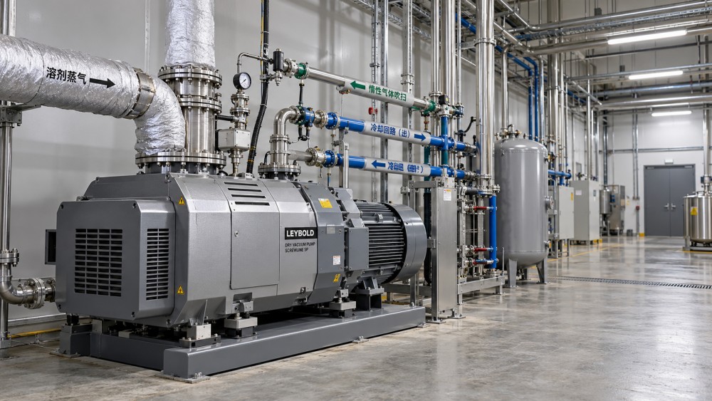
A dry pump has no sealing liquid in its pumping chamber, but that does not make it immune to liquid formation during solvent handling.
Vapor can condense in inlet piping, internal compression stages, exhaust passages, or downstream equipment. Liquid formed outside the pump may also drain back into it.
Compression increases total pressure and can increase solvent partial pressure. Although compression also heats the gas, nearby metal surfaces may remain colder during transient operation.
The relevant comparison is local solvent dew point against local gas and surface temperatures. An inlet temperature reading alone cannot establish that every internal stage remains dry.
Mixed solvent streams need additional attention because composition changes during drying, evaporation, or batch transitions. Water vapor may introduce another condensation mechanism or corrosion concern.
Ask the manufacturer to assess the actual solvent mixture, vapor throughput, suction pressure, exhaust pressure, and operating sequence before accepting a condensation prevention strategy.
Which operating information should you check before changing settings?
Start with the pump manual and application approval. Confirm permitted solvents, vapor capacity, temperature limits, cooling requirements, purge specifications, and allowable inlet and exhaust pressures.
Record solvent identity and composition, including water, cleaning agents, and likely contaminants. Compatibility must cover seals, coatings, elastomers, and any exposed internal construction materials.
Capture the operating range rather than one normal reading. Include startup conditions, maximum evaporation rate, final drying pressure, batch changeovers, and periods of reduced throughput.
Log suction pressure, available pump temperatures, cooling supply conditions, purge flow, motor current, and exhaust pressure. Compare trends at similar points within successive batches.
Confirm where sensors are installed and what they measure. A casing sensor, coolant outlet sensor, and discharge gas sensor provide different information about condensation risk.
If composition or vapor loading is uncertain, involve process engineering before changing controls. Guessing from solvent boiling points at atmospheric pressure can produce misleading conclusions.
How should you set pump temperature and cooling?
Use the manufacturer’s solvent service temperature guidance, including its approved control settings. The objective is sufficient thermal margin wherever condensation could damage the pump.
A solvent’s atmospheric boiling point is not a suitable pump temperature setpoint. Dew point depends on solvent partial pressure, which changes through the system.
Some dry vacuum pumps regulate temperature through cooling circuits, thermostatic valves, or control software. Others offer limited adjustment and require application changes or different equipment.
Do not restrict cooling water experimentally to make the pump hotter. Inadequate cooling can overheat bearings, distort clearances, damage seals, or trigger protective shutdowns.
Excessive cooling can also undermine an approved thermal strategy. Check supply temperature, flow, valve operation, fouling, and seasonal changes against the manufacturer’s stated requirements.
Higher temperature may accelerate polymerization, decomposition, or deposit formation with reactive materials. Check solvent stability and contaminant behavior before treating additional heat as the solution.
When the required thermal margin exceeds equipment limits, reduce vapor loading or improve upstream separation. Forcing a temperature setting cannot resolve an unsuitable application.
When will gas ballast or inert purge help?
Where provided, gas ballast introduces gas at a designated pumping stage. This can reduce the solvent fraction and improve condensable vapor handling under specified conditions.
An inert process purge may also dilute vapors or protect selected internal spaces. Its effect depends on injection location, flow, pressure, and pump design.
Do not assume every purge connection prevents condensation throughout the pump. A bearing protection purge may serve a different purpose from gas entering compression stages.
For flammable solvents, introducing air through a ballast connection can create an ignitable mixture. Use only the gas and arrangement approved for the application.
Nitrogen is commonly considered, but specifying nitrogen alone does not establish safety. Gas reliability, oxygen concentration, operating transitions, and the complete exhaust system still matter.
Use the approved flow measurement and regulation method. A supply pressure reading does not prove adequate purge flow through a restricted line or faulty valve.
Additional gas can affect ultimate pressure, pumping performance, exhaust treatment capacity, and operating cost. Adjust within documented limits, then verify process results and temperature trends.
What startup sequence reduces the risk of a wet pump?
Before startup, verify cooling availability, approved purge supply, exhaust routing, and any separator drain status. Confirm valves follow the documented sequence for that installation.
Start and warm the pump according to manufacturer instructions before admitting significant solvent vapor. Elapsed time alone is less useful than the specified readiness criteria.
A warm external casing does not necessarily mean every internal surface has reached suitable conditions. Use validated temperature indications or the manufacturer’s prescribed warmup procedure.
Bring solvent loading into the system gradually when the process permits. Sudden evaporation can exceed the pump’s vapor capacity even when normal production remains acceptable.
Check upstream vessels and piping for pooled liquid before opening the vacuum path. A liquid slug presents a different problem from vapor condensing internally.
Include brief interruptions in the operating procedure. A pump that cools during a hold period may require renewed conditioning before the next solvent exposure.
How do you manage vapor peaks, piping, and condensers?
Peak vapor throughput often matters more than batch average consumption. Rapid pressure reduction, increased heating, or charging a warm vessel can sharply increase evaporation.
Where production allows, moderate the pressure ramp or heat input to keep vapor delivery within approved capacity. Coordinate these changes with the process owner.
An upstream condenser can reduce solvent loading, provided its temperature, pressure drop, capacity, and control response suit the actual duty across the batch cycle.
A knockout vessel separates entrained liquid, but does not automatically remove solvent vapor. Confirm which problem each component is intended to solve before modifying equipment.
Inspect piping for cold spots, low points, and arrangements that allow condensate to return toward the pump. Drainage provisions must suit vacuum service and solvent hazards.
Insulation or heat tracing may help selected lines, but requires an engineered temperature limit and suitable equipment. Avoid transferring an uncontrolled heat source into hazardous service.
Check exhaust restrictions and downstream condensate accumulation as well. Increased backpressure changes pump conditions, while poorly arranged discharge piping can allow liquid to drain backward.
What should happen before shutdown or an extended idle period?
Stopping immediately after solvent service can leave vapor inside a cooling pump. As internal temperatures fall, retained solvent may condense on vulnerable surfaces overnight.
Follow the approved sequence for stopping solvent admission, isolating the process, and maintaining any required pumping or inert purge period before the final shutdown.
A timed clearing period should come from manufacturer guidance or a validated site procedure. There is no universal duration that suits every solvent and installation.
Where monitoring is available, use appropriate process indicators to confirm clearing performance. Continued purge flow alone does not demonstrate that trapped solvent has been removed.
Do not close or isolate the exhaust while the pump is running unless the equipment explicitly permits that arrangement. Pressure buildup can create serious hazards.
For longer storage, follow preservation instructions covering residual chemicals, moisture, isolation, and restart checks. Document any abnormal shutdown so the next operator understands the condition.
Which warning signs deserve investigation during a shift?
Watch for declining pumping performance, unusual motor current, unstable temperatures, repeated trips, new noise, or liquid appearing where it was previously absent during operation.
These symptoms do not prove condensation. Leaks, fouling, cooling faults, process changes, and mechanical wear can produce similar effects, so use trends to narrow causes.
If symptoms begin after a recipe change, compare solvent composition and vapor loading first. If they follow maintenance, verify valve positions, cooling configuration, and sensor readings.
When exhaust pressure rises, inspect the approved downstream checks for restrictions, flooded collection points, or treatment equipment problems. Follow isolation procedures before opening any component.
Avoid repeated restarts after unexplained trips or suspected liquid ingestion. Follow site shutdown criteria and obtain manufacturer guidance before attempting to restore normal operation.
Record what changed, when symptoms appeared, and which readings moved first. This gives maintenance and process engineering a stronger basis for correcting the underlying cause.
How do you verify that prevention measures are working?
Evaluate changes across representative batches, including the highest expected vapor load and relevant ambient conditions. One successful warm run does not establish reliable year round performance.
Compare cycle time, achieved pressure, temperature stability, purge consumption, exhaust behavior, and maintenance findings. A useful improvement protects reliability while preserving required process performance.
Inspect accessible collection points and service findings under approved procedures. Reduced deposits or corrosion over an appropriate interval provides evidence beyond a single temperature reading.
Keep the approved operating window visible to operators, with clear responses for deviations. Include warmup readiness, maximum loading conditions, purge requirements, and shutdown sequencing.
Where flammable vapors are involved, confirm applicable local requirements and equipment suitability with the responsible site specialists. Certification and operating obligations depend on jurisdiction and installation.
Keep the full operating cycle within the approved envelope
Condensation prevention succeeds when temperature, solvent loading, gas management, and operating sequences work together. Reliable dry vacuum pumps depend on conditions throughout the cycle.
Prioritize verified warmup, controlled vapor admission, correct cooling, suitable ballast or purge, and effective clearing before shutdown. Escalate conditions that exceed the approved envelope.
When troubleshooting, change settings through the site’s approved process and document results. The best adjustment removes the cause of condensation while maintaining safe, stable production.